Ships and offshore rigs are large, complex vessels which must be self-sustaining in their environment for long periods with a high degree of reliability. A vessel ( rig or ship ) is the product of two main areas of skill, those of the naval architect and the marine engineer. The naval architect is concerned with the hull, its construction, form, habitability, stability, strength and ability to endure its designed offshore environment.

The marine or ship engineer is responsible for the various systems which propel, power and operate the vessel or rig. More specifically, this means the machinery required for power, propulsion, anchoring and securing, cargo handling, HVAC air conditioning, marine systems generation and its distribution. Some overlap in responsibilities occurs between naval architects and marine engineers in areas such as propeller design, the reduction of noise and vibration in the ship's or rig structure, and engineering services provided to considerable areas of the vessel.
A vessel might reasonably be divided into three distinct areas: the cargo-carrying and ballast tanks, the accommodation and the machinery spaces. Depending upon the type each vessel will assume varying proportions and functions. An oil tanker, for instance, will have the cargo-carrying region divided into tanks by two longitudinal bulkheads and several transverse bulkheads. There will be considerable quantities of cargo piping both above and below decks. The general cargo ship will have various cargo holds which are usually the full width of the vessel and formed by transverse bulkheads along the ship's length. Cargohandling
equipment will be arranged on deck and there will be large hatch openings closed with steel hatch covers. The accommodation areas in each of these vessel or rig will be sufficient to meet the requirements for the crew, provide a navigating bridge area and a communications centre. The machinery space size will be decided by the particular machinery installed and the auxiliary equipment necessary. A passenger ship, however, would have a large accommodation area, since this might be considered the 'cargo space'. Machinery space requirements will probably be larger because of air conditioning equipment, stabilisers and
other passenger related equipment.
Three principal types of machinery installation are to be found offshore sea today. Their individual merits change with technological advances and improvements and economic factors such as the change in current oil prices. The typical layout may involve the use of direct-coupled slow-speed diesel engines, medium-speed diesels with a gearbox, and the steam turbine with a gearbox drive to the propeller.
A propeller or thruster, in order to operate efficiently, must rotate at a relatively low speed. Thus, regardless of the rotational speed of the prime mover, the propeller shaft must rotate at about 80 to 100 rev/min. The slow-speed diesel engine rotates at this low speed and the crankshaft is thus directly coupled to the propeller shafting. The medium-speed diesel engine operates in the range 250—750 rev/min and cannot therefore be direct coupled to the propeller shaft. A gearbox is used to provide a low-speed drive for the propeller shaft. The steam turbine rotates at a very high speed, in the order of 6000 rev/min. Again, a gearbox must be used to provide a low-speed drive for the propeller shaft.
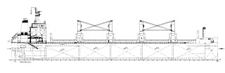
Slow-speed diesel engine
Direct-drive diesel engine may be used in the machinery arrangement. The auxiliaries visible are a diesel generator on the upper flat and an air compressor, below. Other auxiliaries within the machinery space would include additional generators, an oily-water separator, an evaporator, numerous pumps and heat exchangers. An auxiliary boiler and an exhaust gas heat exchanger would be located in the uptake region leading to the funnel. Various workshops and stores and the machinery control room will also be found on the upper flats.
Geared medium-speed diesel
Medium-speed (500rev/min) diesels could be used in the machinery layout. The gear units provide a twin-screw drive at 170rev/min to controllable pitch propellers. The gear units also power take-offs for shaft-driven generators which provide all power requirements while at sea.
The various pumps and other auxiliaries are arranged at floor plate level in this minimum-height machinery space. The exhaust gas boilers and uptakes are located port and starboard against the side shell plating.
The diesel engine is a type of internal combustion engine which ignites the fuel by injecting it into hot, high-pressure air in a combustion chamber. In common with all internal combustion engines the diesel engine operates with a fixed sequence of events, which may be achieved either in four strokes or two, a stroke being the travel of the piston between its extreme points. Each stroke is accomplished in half a revolution of the crankshaft.
Four-stroke cycle

The four-stroke cycle is completed in four strokes of the piston, or two revolutions of the crankshaft. In order to operate this cycle the engine requires a mechanism to open and close the inlet and exhaust valves.
Consider the piston at the top of its stroke, a position known as top dead centre (TDC). The inlet valve opens and fresh air is drawn in as the piston moves down. At the bottom of the stroke, i.e. bottom dead centre (BDC), the inlet valve closes and the air in the cylinder is compressed (and consequently raised in temperature) as the piston rises. Fuel is injected as the piston reaches top dead centre and combustion takes place, producing very high pressure in the gases. The piston is now forced down by these gases and at bottom dead centre the exhaust valve opens. The final stroke is the exhausting of the burnt gases as the piston rises to top dead centre to complete the cycle. The four distinct strokes are known as 'inlet' (or suction), 'compression', 'power' (or working stroke) and 'exhaust'
Two Stroke Engine
The two-stroke cycle is completed in two strokes of the piston or one revolution of the crankshaft. In order

Consider the piston at the top of its stroke where fuel injection and combustion have just taken place. The piston is forced down on its working stroke until it uncovers the exhaust port. The burnt gases then begin to exhaust and the piston continues down until it opens the inlet or scavenge port. Pressurised air then enters and drives out the remaining exhaust gas. The piston, on its return stroke, closes the inlet and exhaust ports. The air is then compressed as the piston moves to the top of its stroke to complete the cycle.
The main difference between the two cycles is the power developed. The two-stroke cycle engine, with one working or power stroke every revolution, will, theoretically, develop twice the power of a four-stroke engine of the same swept volume. Inefficient scavenging however and other losses, reduce the power advantage to about 1.8. For a particular engine power the two-stroke engine will be considerably lighter—an
important consideration for ships. Nor does the two-stroke engine require the complicated valve operating mechanism of the four-stroke.
The four-stroke engine however can operate efficiently at high speeds which offsets its power disadvantage; it also consumes less lubricating oil.
Each type of engine has its applications which on board ship or rig have resulted in the slow speed (i.e. 80— 100 rev/min) main propulsion diesel operating on the two-stroke cycle. At this low speed the engine requires no reduction gearbox between it and the propeller. The four-stroke engine (usually rotating at medium speed, between 250 and 750 rev/min) is used for auxiliaries such as alternators and sometimes for main propulsion with a gearbox to provide a propeller speed of between 80 and 100 rev/min.
There are two possible measurements of engine power: the indicated power and the shaft power. The indicated power is the power developed within the engine cylinder and can be measured by an engine indicator.
The shaft power is the power available at the output shaft of the engine and can be measured using a torsionmeter or with a brake.
Fuel oil supply for a two-stroke diesel
A slow-speed two-stroke diesel is usually arranged to operate continuously on heavy fuel and have available a diesel oil supply for manoeuvring conditions.
In the system, the oil is stored in tanks in the double bottom from which it is pumped to a settling tank and heated. After passing through centrifuges the cleaned, heated oil is pumped to a daily service tank. From the daily service tank the oil flows through a three-way valve to a mixing tank. A flow meter is fitted into the system to indicate fuel consumption. Booster pumps are used to pump the oil through heaters and a viscosity regulator to the engine-driven fuel pumps. The fuel pumps will discharge high-pressure fuel to their respective injectors.
The viscosity regulator controls the fuel oil temperature in order to provide the correct viscosity for combustion. A pressure regulating valve ensures a constant-pressure supply to the engine-driven pumps, and a pre-warming bypass is used to heat up the fuel before starting the engine. A diesel oil daily service tank may be installed and is connected to the system via a three-way valve. The engine can be started up and
manoeuvred on diesel oil or even a blend of diesel and heavy fuel oil. The mixing tank is used to collect recirculated oil and also acts as a buffer or reserve tank as it will supply fuel when the daily service tank is empty.
The system includes various safety devices such as low-level alarms and remotely operated tank outlet valves which can be closed in the event of a fire.
Cooling
Cooling of engines is achieved by circulating a cooling liquid around internal passages within the engine. The cooling liquid is thus heated up and is in turn cooled by a sea water circulated cooler. Without adequate cooling certain parts of the engine which are exposed to very high temperatures, as a result of burning fuel, would soon fail. Cooling enables the engine metals to retain their mechanical properties. The usual coolant used is fresh water: sea water is not used directly as a coolant because of its corrosive action. Lubricating oil is sometimes used for piston cooling since leaks into the crankcase would not cause problems. As a result of its lower specific heat however about twice the quantity of oil compared to water would be required.
Fresh water cooling system

A water cooling system for a slow-speed diesel engine is shown. It is divided into two separate systems: one for cooling the cylinder jackets, cylinder heads and turbo-blowers; the other for piston cooling.
The cylinder jacket cooling water after leaving the engine passes to a sea-water-circulated cooler and then into the jacket-water circulating pumps. It is then pumped around the cylinder jackets, cylinder heads and turbo-blowers. A header tank allows for expansion and water make-up in the system. Vents are led from the engine to the header tank for the release of air from the cooling water. A heater in the circuit facilitates warming of the engine prior to starting by circulating hot water.
The piston cooling system employs similar components, except that a drain tank is used instead of a header tank and the vents are then led to high points in the machinery space. A separate piston cooling system is
used to limit any contamination from piston cooling glands to the piston cooling system only.
Sea water cooling system

The various cooling liquids which circulate the engine are themselves cooled by sea water. The usual arrangement uses individual coolers for lubricating oil, jacket water, and the piston cooling system, each cooler being circulated by sea water. Some modern ships use what is known as a 'central cooling system' with only one large sea-water-circulated cooler.
This cools a supply of fresh water, which then circulates to the other Individual coolers. With less equipment in contact with sea water the corrosion problems are much reduced in this system.
A sea water cooling system is shown. From the sea suction one of a pair of sea-water circulating pumps provides sea water which circulates the lubricating oil cooler, the jacket water cooler and the piston water cooler before discharging overboard. Another branch of the sea water main provides sea water to directly cool the charge air (for a direct-drive two-stroke diesel).
One arrangement of a central cooling system is shown.

The sea water circuit is made up of high and low suctions, usually on either side of the machinery space, suction strainers and several sea water pumps. The sea water is circulated through the central coolers and then discharged overboard. A low-temperature and high-temperature circuit exist in the fresh water system. The fresh water in the high-temperature circuit circulates the main engine and may, if required, be used as a heating medium for an evaporator. The low-temperature circuit circulates the main engine air coolers, the lubricating oil coolers and all other heat exchangers. A regulating valve controls the mixing of water between the high-temperature and low-temperature circuits.
Starting air system
Diesel engines are started by supplying compressed air into the cylinders in the appropriate sequence for the required direction. A supply of compressed air is stored in air reservoirs or 'bottles' ready for immediate use. Up to 12 starts are possible with the stored quantity of compressed air. The starting air system usually has interlocks to prevent starting if everything is not in order.
Compressed air is supplied by air compressors to the air receivers. The compressed air is then supplied by a large bore pipe to a remote operating non-return or automatic valve and then to the cylinder air start valve.
cylinder air start valve will admit compressed air into the cylinder. The opening of the cylinder valve and the remote operating valve is controlled by a pilot air system. The pilot air is drawn from the large pipe and passes to a pilot air control valve which is operated by the engine air start lever.
When the air start lever is operated, a supply of pilot air enables the remote valve to open. Pilot air for the appropriate direction of operation is also supplied to an air distributor. This device is usually driven by the engine camshaft and supplies pilot air to the control cylinders of the cylinder air start valves. The pilot air is then supplied in the appropriate sequence for the direction of operation required. The cylinder air start valves are held closed by springs when not in use and opened by the pilot air enabling the compressed air direct from the receivers to enter the engine cylinder. An interlock is shown in the remote operating valve line which stops the valve opening when the engine turning gear is engaged. The remote operating valve prevents the return of air which has been further compressed by the engine into the system.
Control and safety devices
Governors
The principal control device on any engine is the governor. It governs or controls the engine speed at some fixed value while power output changes to meet demand. This is achieved by the governor automatically adjusting the engine fuel pump settings to meet the desired load at the set speed. Governors for diesel engines are usually made up of two systems: a speed sensing arrangement and a hydraulic unit which operates on the fuel pumps to change the engine power output.
Mechanical governor
A flyweight assembly is used to detect engine speed. Two flyweights are fitted to a plate or ballhead which rotates about a vertical axis driven by a gear wheel. The action of centrifugal force throws the weights outwards; this lifts the vertical spindle and compresses the spring until an equilibrium situation is reached. The equilibrium position or set speed may be changed by the speed selector which alters the spring compression.
As the engine speed increases the weights move outwards and raise the spindle; a speed decrease will lower the spindle.
The hydraulic unit is connected to this vertical spindle and acts as a power source to move the engine fuel controls. A piston valve connected to the vertical spindle supplies or drains oil from the power piston which
moves the fuel controls depending upon the flyweight movement. engine speed increases the vertical spindle rises, the piston valve rises and oil is drained from the power piston which results in a fuel control movement. This reduces fuel supply to the engine and slows it down. It is, in effect, a proportional controller
Electric governor
The electric governor uses a combination of electrical and mechanical components in its operation. The speed sensing device is a small magnetic pick-up coil. The rectified, or d.c., voltage signal is used in conjunction with a desired or set speed signal to operate a hydraulic unit. This unit will then move the fuel controls in the appropriate direction to control the engine speed.
Crankcase oil mist detector
The presence of an oil mist in the crankcase is the result of oil vaporisation caused by a hot spot. Explosive conditions can result if a build up of oil mist is allowed. The oil mist detector uses photoelectric cells to measure small increases in oil mist density. A motor driven fan continuously draws samples of crankcase oil mist through a measuring tube. An increased meter reading and alarm will result if any crankcase sample contains excessive mist when compared to either clean air or the other crankcase compartments. The rotary valve which draws the sample then stops to indicate the suspect crankcase. The comparator model tests one crankcase mist sample against all the others and once a cycle against clean air. The level model tests each crankcase in turn against a reference tube sealed with clean air. The comparator model is used for crosshead type engines and the level model for trunk piston engines.

Explosion relief valve
As a practical safeguard against explosions which occur in a crankcase, explosion relief valves or doors are fitted. These valves serve to relieve excessive crankcase pressures and stop flames being emitted from the crankcase. They must also be self closing to stop the return of atmospheric air to the crankcase.
Various designs and arrangements of these valves exist where, on large slow-speed diesels, two door type valves may be fitted to each crankcase or, on a medium-speed diesel, one valve may be used. One design of explosion relief valve is shown.
A light springholds the valve closed against its seat and a seal ring completes the joint. A deflector is fitted on the outside of the engine to safeguard personnel from the outflowing gases, and inside the engine, over the valve opening, an oil wetted gauze acts as a flame trap to stop any flames leaving the crankcase. After operation the valve will close automatically under the action of the spring.
Ship Mooring and berthing
In order to design a ship's mooring system, the environment loads likely to act upon the ship must first be

"Mooring" refers to the system for securing a ship or vessel to a terminal or quayside of a yard. The most common terminals for ships are piers and sea islands, however, other shipboard operations such as mooring at Single Point Moorings (SPM's), Multi-Buoy Moorings (MBM's), emergency towing, tug handling, barge mooring, canal transit, lightening and anchoring may fall into the broad category of mooring and thus require specialised fittings or equipment.
The use of an efficient mooring system is essential for the safety of the ship, her crew, the terminal and the environment. The problem of how to optimise the moorings to resist the various forces will be dealt with by answering the following questions:
• What are the forces applied on the ship?
• What general principles determine how the applied forces are distributed to the mooring lines?
• How can the above principles be applied in establishing a good mooring arrangement?
The term 'mooring pattern' refers to the geometric arrangement of mooring lines between the ship and the berth. The most efficient line 'lead' for resisting any given environmental load is a line oriented in the same direction as the load. This would imply that, theoretically, mooring lines should all be oriented in the direction of the environmental forces and be attached at such a longitudinal location on the ship that the resultant load and restraint act through one and the same location.
The effectiveness of a mooring line is influenced by two angles: the vertical angle the line forms with the pier deck and the horizontal angle the line forms with the parallel side of the ship. The steeper the orientation of a line, the less effective it is in resisting horizontal loads.
• Mooring lines should be arranged as symmetrically as possible about the midship point of the ship. (A symmetrical arrangement is more likely to ensure a good load distribution than an asymmetrical arrangement.)
• Breast lines should be oriented as perpendicular as possible to the longitudinal centre line of the ship and as far aft and forward as possible.
• Spring lines should be oriented as parallel as possible to the longitudinal centre line of the ship.
• The vertical angle of the mooring lines should be kept to a minimum.
The 'flatter' the mooring angle, the more efficient the line will be in resisting horizontally-applied loads on the ship.
Head and stern lines are normally not efficient in restraining a ship in its berth. Mooring facilities with good breast and spring lines allow a ship to be moored most efficiently, virtually 'within its own length'. The use of head and stern lines requires two additional mooring dolphins and decreases the overall restraining efficiency of a mooring pattern when the number of available lines is limited.
High winds and currents from certain directions might make it desirable to have an asymmetrical mooring arrangement. This could mean placing more mooring lines or breast lines at one end of the ship.
The other factor to consider is the optimum length of mooring lines. It would be desirable to keep all lines at a vertical angle of less than 25°. For example, if the ship's chock location is 25m above the shore mooring point, the mooring point should be at least 50m horizontally from the chock.
Long lines are advantageous both from standpoint of load efficiency and line-tending. But where fibre ropes are used, the increased extension can be a disadvantage by permitting the ship to move excessively, thereby endangering loading arms.
The terminal or quayside can utilize a number of concepts in modern mooring management to reduce the possibility of ship break-out.
These are:
• To develop guidelines for the safe mooring of vessels for the operating environment existing at the terminal.
• To obtain information from the ship prior to arrival concerning the ship's mooring equipment
• To examine the ship's mooring equipment after berthing to determine what modification, if any, must be made to standard guidelines in view of the state of maintenance, training of crew, etc.
• To inspect line lending periodically either visually or by the instrumentation of mooring hooks.
• To take whatever action is deemed appropriate to ensure stoppage of cargo transfer, disconnection of loading arms and removal from berth of the ship should the ship fail to take appropriate measures to ensure safety of mooring.
As soon as practicable after berthing, it is recommended that terminals have their representative board the vessel to establish contact with the Master or his designated representative. At this meeting the Terminal Representative should provide information relating to shore facilities and procedures.
In addition he should in concert with the Ship Representative:
• Complete the Ship/Shore Safety Check List in line with guidance given and, where appropriate, physically check items before ticking off.
• Obtain details of moorings and winches, including state of maintenance.
• Review forecasted weather and arrange for the Master to be advised of any expected changes.
• Assess freeboard limitations.
• Assess type and condition of ship mooring equipment and its ballasting ability.
Overloading of mooring lines is evidenced in a number of ways; for example, by direct measurements of mooring line loads, by direct observation of the moorings by experienced personnel, or by predictions made by those having a knowledge of the effects of wind and current on the ship mooring system or by winch slippage.
The following precautions are likely to apply:
• Harden-up on the winch brakes, Do not release brakes and attempt to heave in
• Discontinue cargo operations
• Reduce freeboard by taking-on ballast if loads are due to high wind conditions.
• Disconnect loading arms and gangways.
• Call out crew, linemen, mooring boats, tugs and put ship's engines on readiness.
• Run extra moorings as available together with any shore mooring available to augment ship's equipment.
• In emergencies place winches in gear.
No comments:
Post a Comment